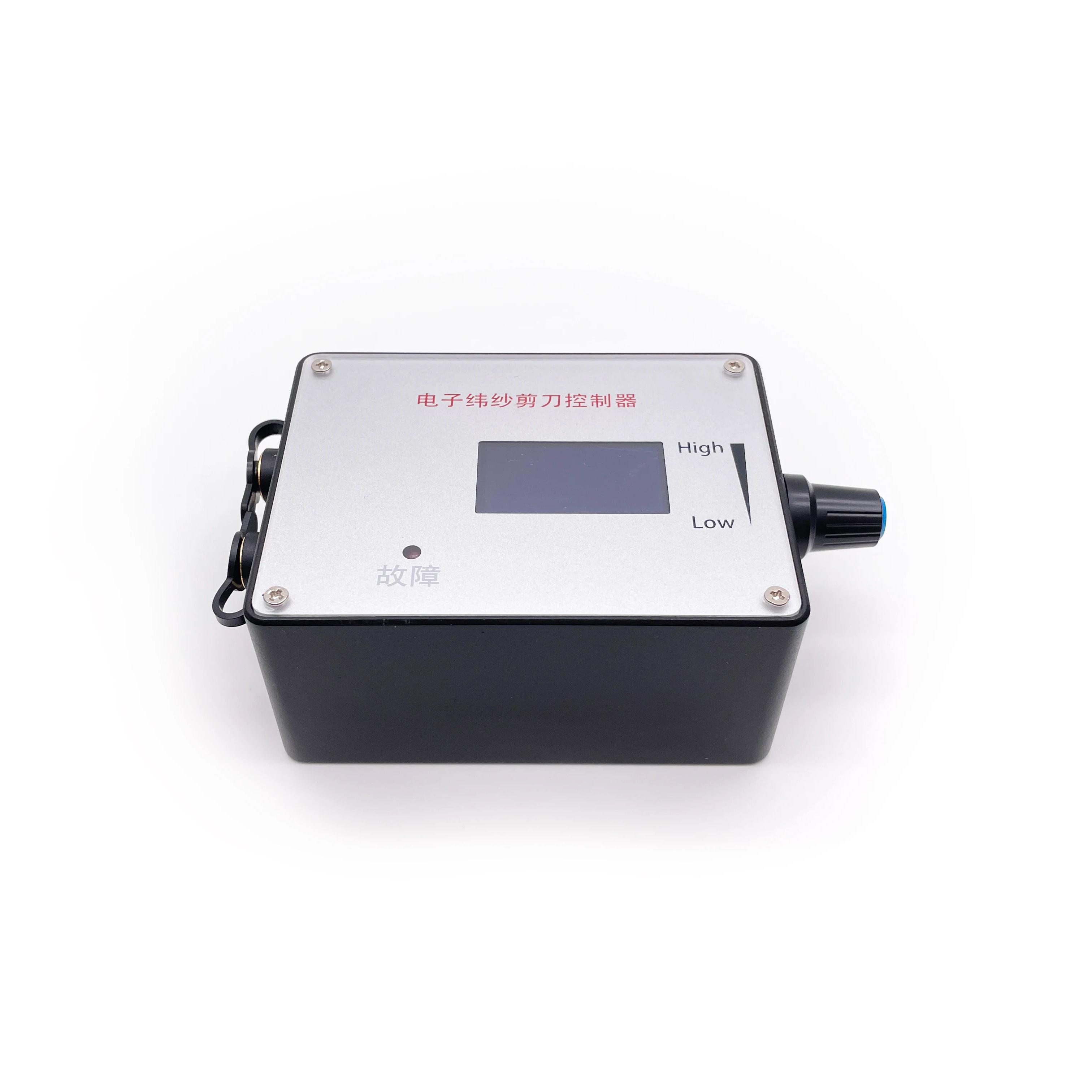
Motor Speed Controller, DC 5V-36V 3-Phase Brushless Motor Speed Control CW CCW Reversible Switch

Product Description

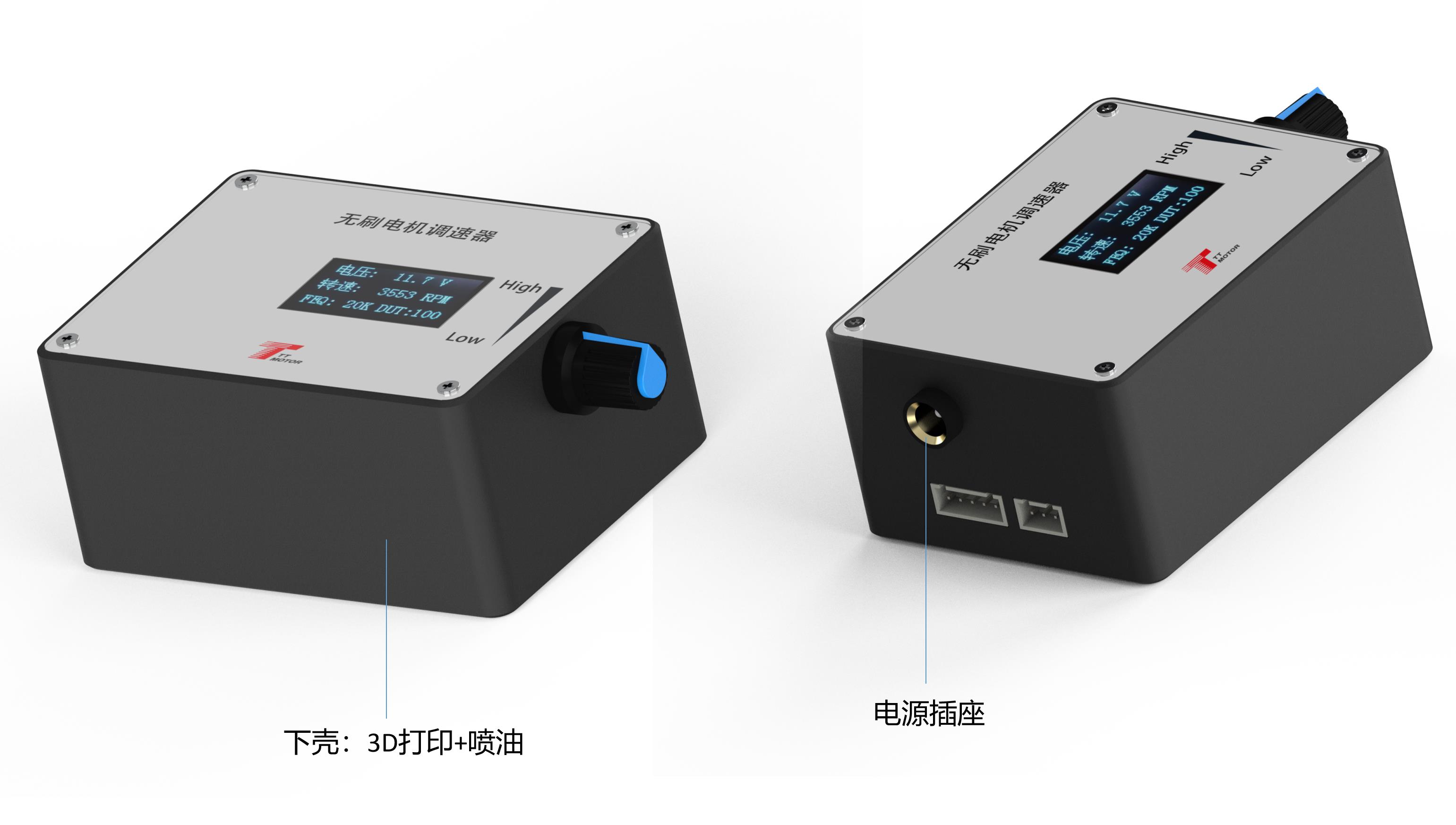
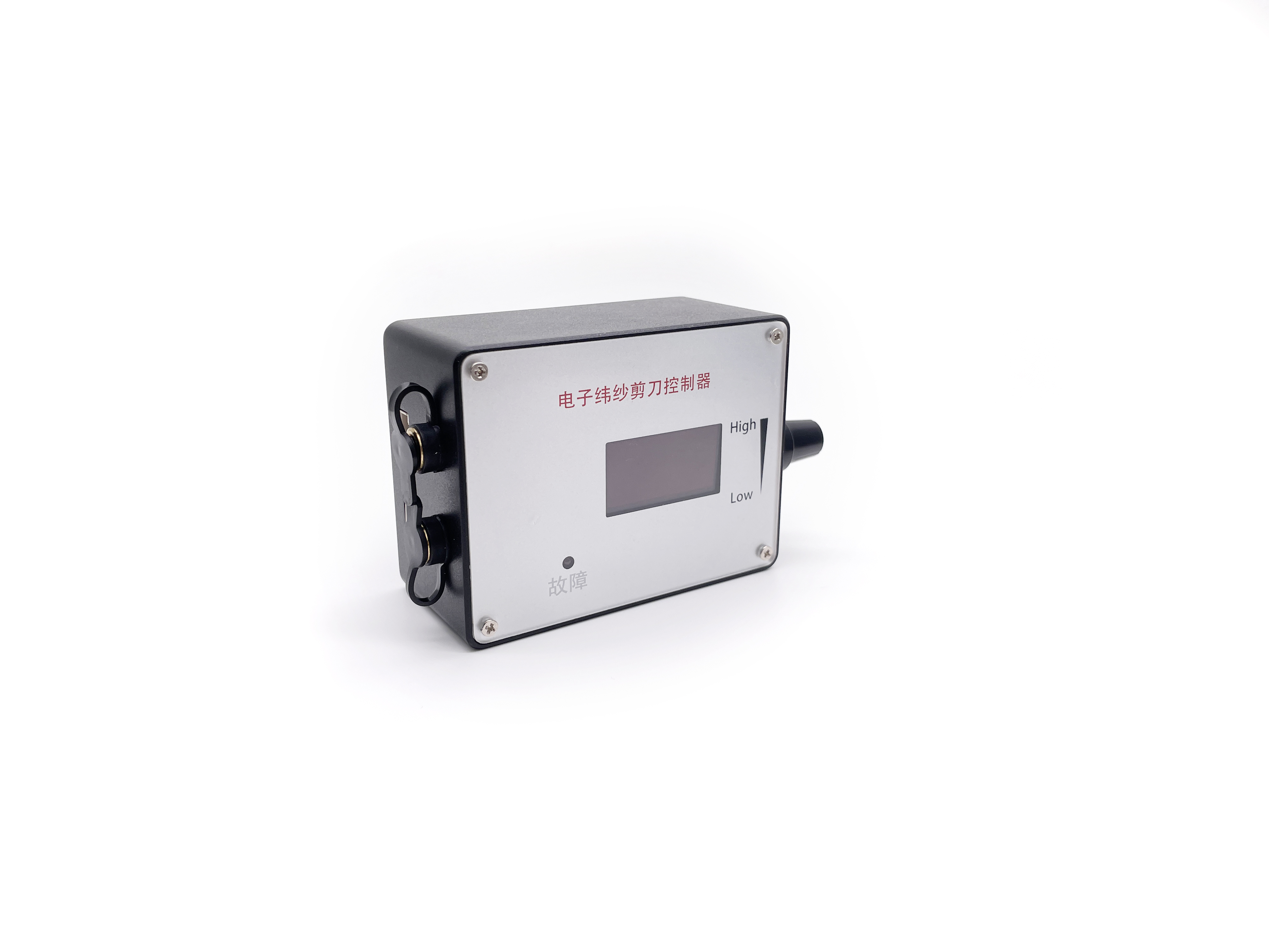
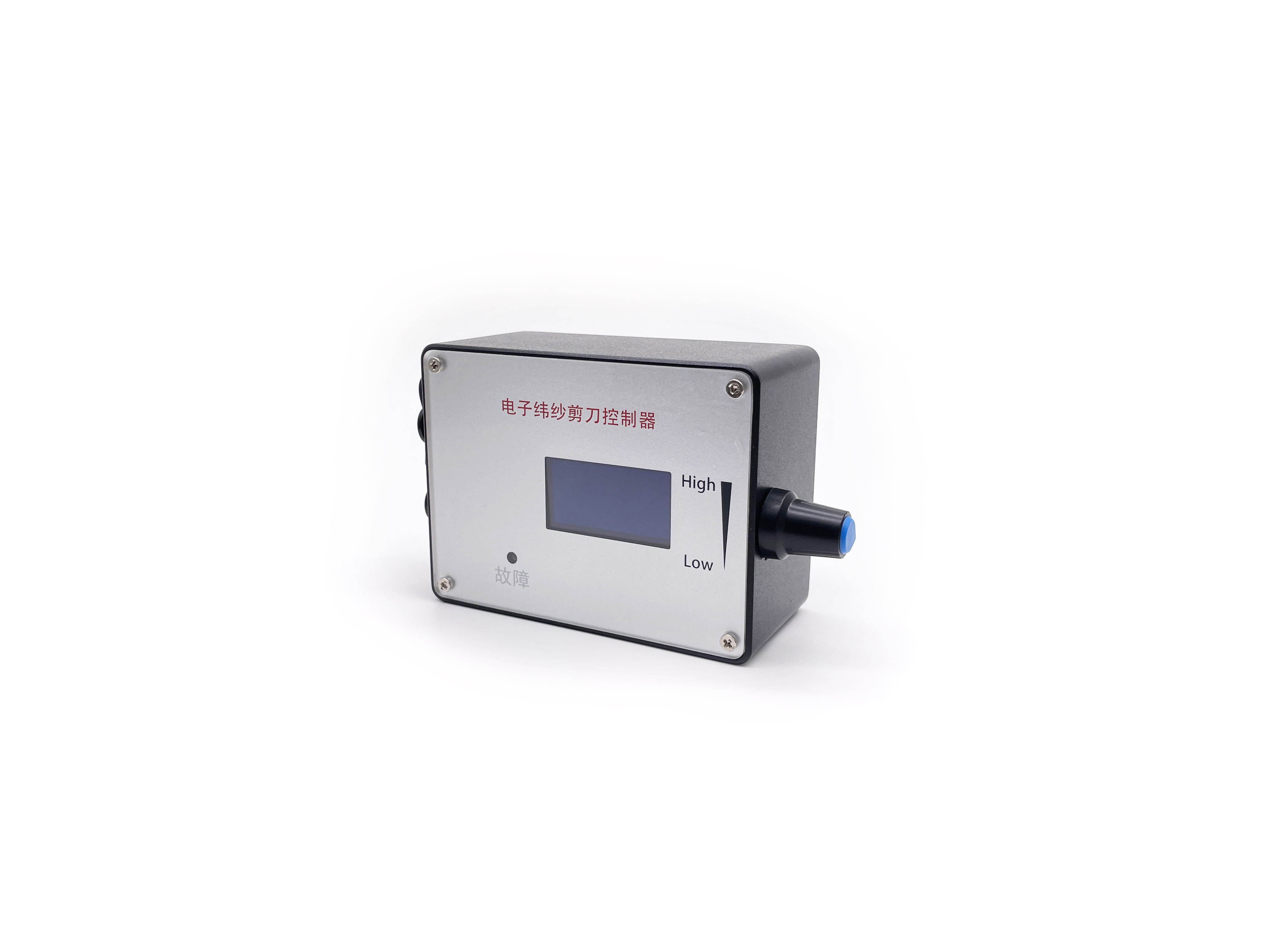
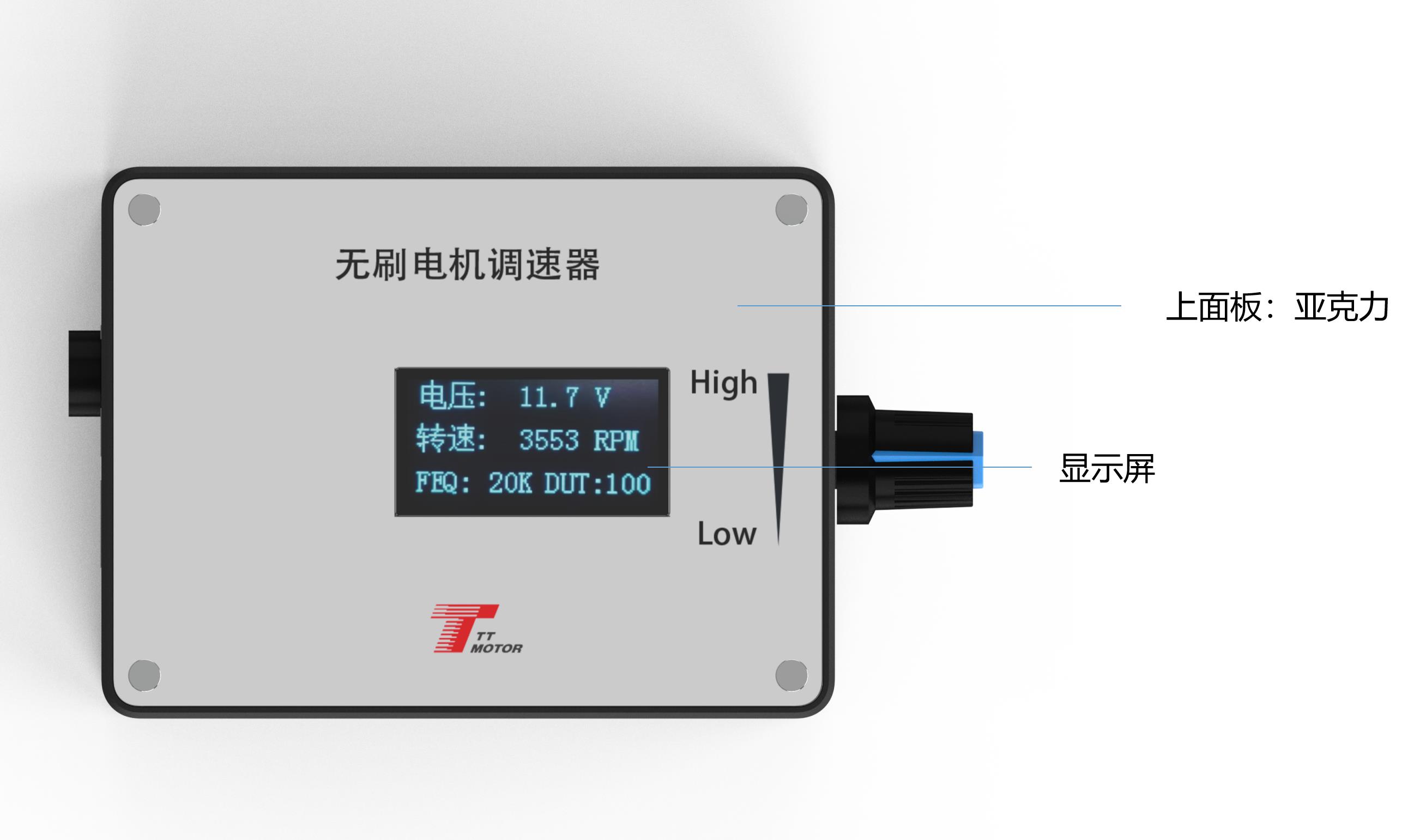
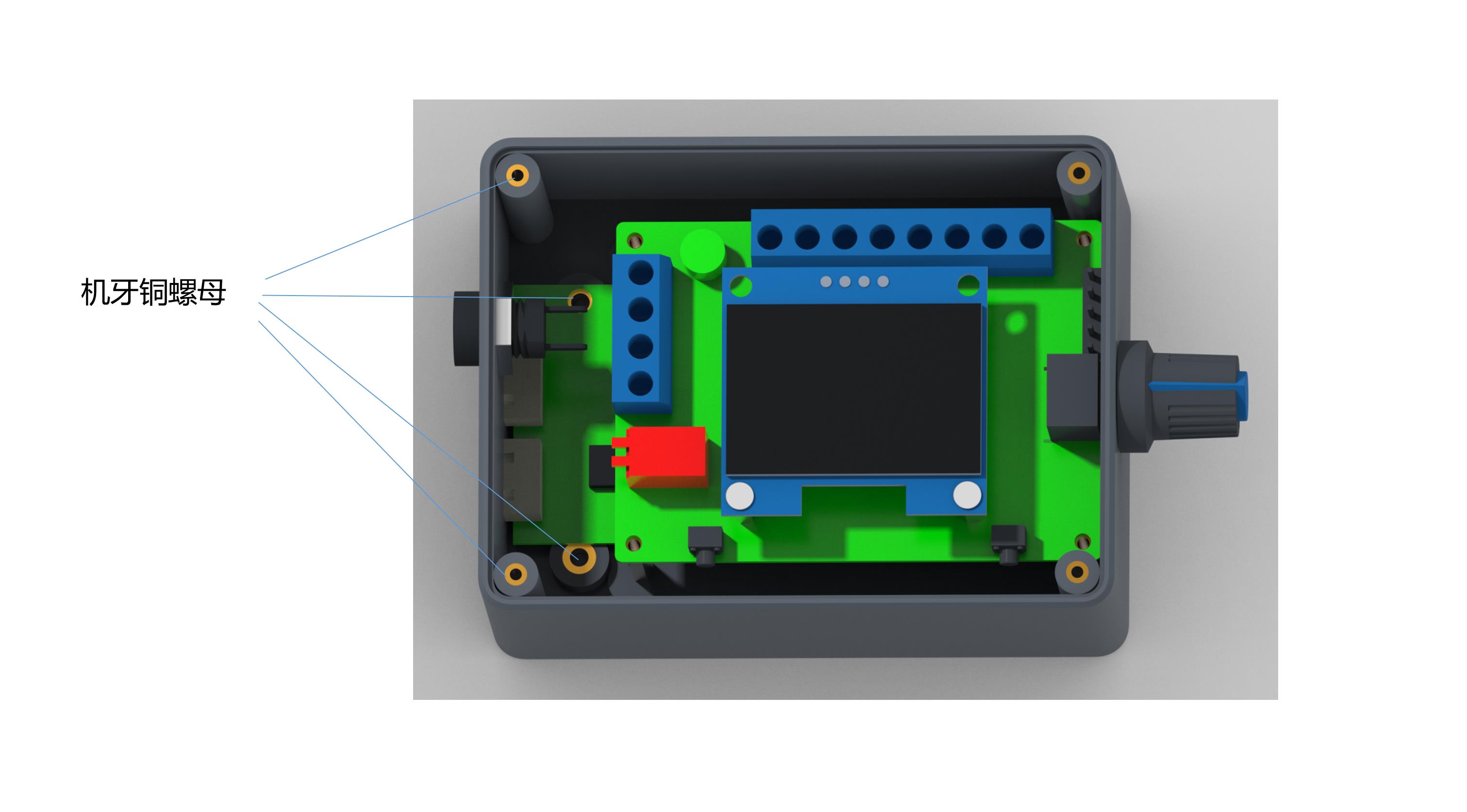
Governor Layout
Electrical Performance Specifications of Governor
Voltage Range: DC 5V-28V.
🔌
Rated Current: MAX 2A. To control the motor with greater current, the motor power line is directly connected to the power supply, not through the governor.
🎛️
PWM Output Frequency: 0 ~ 100KHz.
📈
Analog Voltage Output: 0-5V.
🌡️
Working Temperature: -10°C - 70°C
Storage Temperature: -30°C - 125°C
📐
Driver Board Size: Length 60mm X Width 40mm.
Governor Wiring and Internal Function Description
1
Governor, motor power supply positive input.
2
Governor, motor power input negative.
3
The positive output of the power supply of the motor.
4
Negative output of the power supply of the motor.
5
High and low level output of positive and negative rotation control. High level 5V, low level 0V, controlled by touch switch 2 (F/R). The default is high level.
6
High and low level output of brake control. High level 5V, low level 0V, controlled by touch switch 1 (BRA). Power on default is high level.
7
Analog voltage output (0~5V). This interface is suitable for accepting analog voltage speed regulation motor.
8
PWM1 reverse output. This interface is suitable for the motor that accepts PWM speed regulation, and the speed is inversely proportional to the duty cycle.
9
PWM2 forward output. This interface is suitable for motors that accept PWM speed regulation, and the speed is proportional to the duty cycle.
Signal Adjustment (6-9): The output signal changes of the three interfaces are adjusted by the potentiometer.

Feedback Input (10): Motor feedback signal input.
Note: FG/FG*3 should be based on the actual motor feedback times whether to add a jumper cap. No jumper cap is a single times FG; an added jumper cap is 3 times FG*3. The same rules apply for CW/CCW.
Governor Parameter Settings
Setting 1
Frequency Setting
Press and hold the touch switch 1 before power-on and do not release. Power the governor board. Wait until the screen displays "FEQ:20K" before releasing the button. Touch switch 1 to reduce and touch switch 2 to add. The adjustable frequency is specified to the target frequency; the factory default is 20KHz.
Setting 2
Number of Poles Setting
Before power-on, hold down light touch switch 1 and light touch switch 2 simultaneously. Power the governor board and wait until the screen shows "number of poles: 1 polarity" before releasing. Touch switch 1 to reduce and switch 2 to add. Set this to the designed pole number of the motor; the factory default is 1 pole.
Setting 3
Feedback Setting
The FG/FG*3 pin is set as the feedback multiple. Set according to whether the feedback multiplier of the motor is single times FG or three times FG. Adding the jumper cap sets it to 3 times FG; not adding the jumper cap sets it to a single times FG.
Setting 4
Direction Setting
The CW/CCW pin is the direction setting of the motor in its initial state. It is configured according to whether the motor is CW or CCW when the motor direction control line is suspended. CCW is selected with the skip cap added; CW is selected without the skip cap.
Main Screen Display: The current screen displays the input voltage, speed, frequency, and duty cycle. The speed must be properly configured (FG/FG*3, pole number) to display normally.
Governor Precautions
⚠️
The positive and negative power supply of the governor must be connected in accordance with the instructions and must not be reversed. Otherwise, the governor will not function and can burn out.
⚠️
The governor is designed to match motors using the specified control interfaces.
⚠️
The five ports (5-9) must not access a voltage exceeding 5V.
Frequently Asked Questions (FAQ)
Q1: What is the operating voltage and current range of this governor?
A1: The governor operates within a voltage range of DC 5V-28V, and supports a rated current up to MAX 2A. If you need to control a motor requiring greater current, the motor power line must be connected directly to the power supply instead of through the governor.
Q2: How do I change the default frequency setting?
A2: Before powering on the board, press and hold touch switch 1. Turn on the power and release the switch when "FEQ:20K" is displayed. Use switch 1 to decrease the frequency and switch 2 to increase it. The factory default frequency is 20KHz.
Q3: How do I configure the motor's pole number on the governor?
A3: Hold down both touch switch 1 and touch switch 2 simultaneously, then power on the governor board. When the screen displays "number of poles: 1 polarity", release the buttons. You can decrease the value using switch 1 and increase it using switch 2. The factory default is 1 pole.
Q4: What happens if the power supply polarity is connected incorrectly?
A4: The positive and negative power connections must be wired exactly according to the instructions. Reversing the power connection will prevent the governor from working and will burn out the unit.
Q5: How do I set the motor feedback settings for FG and FG*3?
A5: Set the feedback multiplier via the FG/FG*3 pin. If you do not add a jumper cap, it defaults to a single times FG. If you add the jumper cap, it increases the feedback multiplier to 3 times FG (FG*3).
Q6: What is the maximum voltage permitted for the control ports?
A6: The control interfaces (ports 5 through 9) are sensitive and must not be exposed to a voltage higher than 5V. Doing so may damage the control circuitry.
Related Products