What Is a Planetary Gear Motor and How Does It Work?
A Planetary Gear Motor combines a compact electric motor with a planetary gear system. Its name sounds complex. Its operating idea is surprisingly clear. Several small planet gears rotate around a central sun gear. An outer ring gear controls their movement. This arrangement shares torque across multiple contact points, allowing strong output from a relatively small housing.
Robert L. Norton, a respected machine-design author, notes, “Gears are among the oldest and most useful machine elements.” That observation remains relevant in modern motors. A Planetary Gear Motor can deliver higher torque, lower output speed, and improved load distribution. Picture a motor driving a conveyor roller. The motor spins quickly, while the gearbox turns the roller slowly and steadily. The planets help manage that difference.
The mechanism still has limitations. More gears mean more contact surfaces, possible friction, and tighter manufacturing requirements. A smaller motor is not automatically better. Heat, lubrication, backlash, noise, and service life must be evaluated together. This is where many simple explanations become incomplete. Real performance depends on tooth geometry, materials, bearing support, and the applied load.
This guide explains how the gears interact, how speed and torque change, and why engineers choose planetary designs. It also examines practical trade-offs in robotics, automation, medical equipment, and electric mobility. The goal is not to present the system as perfect. It is to show what happens inside the housing, where precision and compromise work together.
Planetary Gear Motor: Definition and Core Components
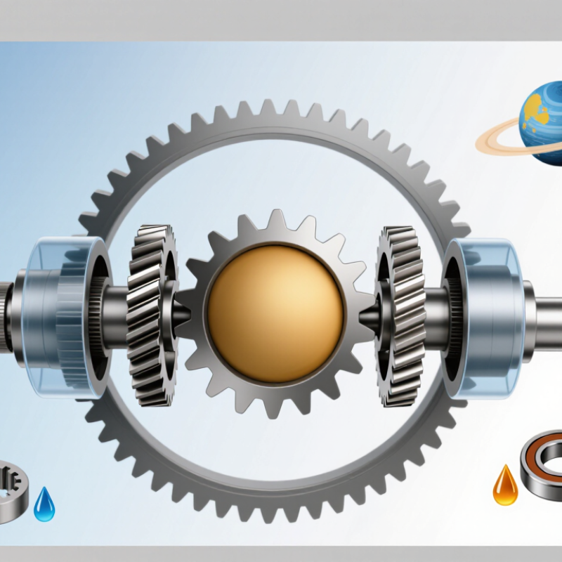
A planetary gear motor combines an electric motor with a compact planetary gearbox. Its name comes from three moving parts: the sun gear, planet gears, and ring gear. The motor usually drives the sun gear at high speed. Several planet gears rotate around it while meshing with the internal ring gear. A carrier holds the planets and delivers the reduced-speed output.
This arrangement shares load across multiple teeth, improving torque density and reducing the gearbox’s overall length. Common designs use steel gears, needle bearings, seals, a housing, and an encoder for position feedback. The output shaft may connect to the carrier, ring gear, or sun gear, depending on the required speed ratio. Higher ratios can demand additional stages. More stages also increase losses.
Performance depends on lubrication, alignment, temperature, and load cycles. It is not magic. A planetary motor can become noisy or inefficient when poorly selected. The U.S. Department of Energy reports that motor-driven systems consume more than half of industrial electricity, making efficiency and maintenance important engineering concerns. Industry market analyses also identify automation, robotics, and electric mobility as major demand areas for compact gear systems. However, reported efficiency values should be checked carefully. Some figures reflect the motor alone, while others include the gearbox, controller, and encoder. That difference can change a comparison significantly.
FAQS
It combines an electric motor with a compact planetary gearbox. The motor drives a central sun gear. Several planet gears transfer torque through multiple contact points.
Electrical current creates magnetic force inside the motor. This force rotates the motor shaft and sun gear. The planet gears spin and travel around the sun gear.
The answer depends on the fixed component and tooth counts. With a stationary ring gear, the planet carrier commonly provides output. It turns slower but delivers higher torque.
The design produces high torque in a small package. Multiple gears share the load across several contact points. It can also provide strong radial support for demanding equipment.
Common applications include robotic joints, conveyor drives, and positioning equipment. Repeated starts and stops can be handled effectively when sizing is correct. Compact spaces benefit from the motor’s high torque density.
Friction, tooth backlash, heat, and alignment errors reduce efficiency. Each gear contact introduces another possible source of loss. Proper lubrication helps, but it cannot remove every limitation.
Frequent reversing cycles can create heat inside an enclosed machine. Limited cooling may raise temperatures, even within the stated power range. This warning is easy to miss.
They should check unusual noise, temperature rise, shaft play, and lubricant condition. Hidden tooth stress may exist while the motor still turns normally. A quiet inspection is not enough.
Engineers should consider starting torque, peak torque, duty cycle, and shock loads. Mounting stiffness, ambient temperature, lubrication, and cooling also matter. Rated output speed alone is not sufficient.
Oversizing may reduce mechanical stress and improve reliability. However, it can increase weight, energy use, and system cost. The larger option is not automatically better.
Conclusion
A Planetary Gear Motor combines an electric motor with a compact planetary gearbox to deliver controlled speed, higher torque, and improved mechanical efficiency. Its main components include the sun gear, planet gears, planet carrier, and ring gear. By arranging several planet gears around the central sun gear, the system distributes load across multiple contact points, creating a strong and balanced transmission structure in a relatively small space.
During operation, the motor drives one gear element while another remains fixed or acts as the output. The planet gears rotate around their own axes and orbit the sun gear, converting the motor’s high-speed rotation into slower, more powerful output motion. This design offers high torque density, smooth operation, durability, and flexible reduction ratios, although it may involve greater cost, assembly complexity, and sensitivity to lubrication or alignment. Planetary Gear Motors are commonly used in robotics, automation equipment, mobility systems, medical devices, and precision machinery. Selection should consider torque, speed, duty cycle, noise, efficiency, mounting space, and operating environment.
